[ CABLE / ADAPTER RECORD // DVI-D SINGLE-LINK TMDS ]
DVI-D Single-Link Digital Video Cable
Digital-only DVI-D 18+1 layout; one TMDS link and no analog VGA pins.
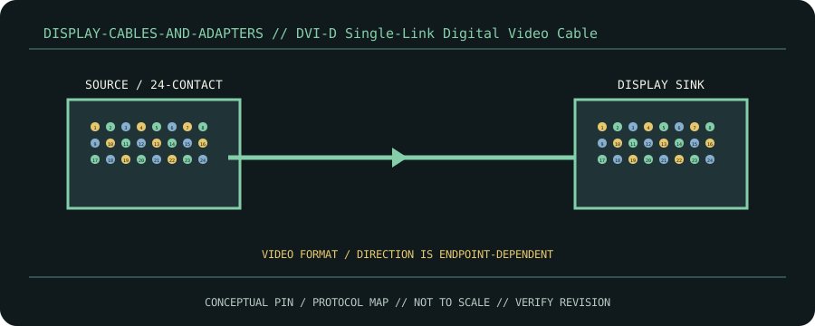
CLASSIFICATION: Display cables and adapters. Identify protocol, direction, pinout and exact cable revision before connection.
Interface and capability
| Standard / protocol | DVI-D single-link TMDS. Connector appearance alone does not establish compatibility. |
|---|---|
| Endpoint / pinout | Digital-only DVI-D 18+1 layout; one TMDS link and no analog VGA pins. |
| Capability / limits | Common 165 MHz pixel clock / 1920×1200 at 60 Hz class; actual timing depends on source, sink and cable. |
| Certification / length | Standards define interface requirements, not every assembly’s performance. Certification, mode, current/power rating, direction and maximum length belong to the exact product/revision and complete channel; verify its manufacturer specification. Do not infer certification from connector shape or marketing terminology. |
Compatibility & handling
- Single-link cable stays single-link even in dual-link sockets. It cannot carry analog VGA; confirm EDID and HDCP support.
- Inspect connector keying, latch, contact condition, shielding, jacket and model/revision marking. Stop if contacts are bent, loose, scorched, corroded or mismatched.
- Route without tension or sharp bends; follow product bend-radius, strain-relief, current and environmental limits. Test at the intended protocol and mode—physical fit is not a compatibility test.
Sources & further reading
- DDWG Digital Visual Interface Revision 1.0Primary standards-body or manufacturer reference for DVI-D single-link TMDS; confirm exact cable assembly, certification and revision.